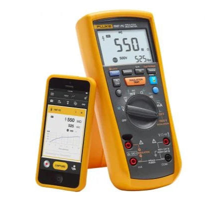
Fluke 1587 FC Insulation Multimeter
Fluke 1587 FC Insulation Multimeter
Couldn't load pickup availability
Keep yourself safe. Find hidden problems faster. Put the paperwork down.
The Fluke 1587 FC insulation multimeter combines a true RMS digital multimeter with insulation testing, Fluke Connect wireless measurement support, CAT IV 600 V / CAT III 1000 V safety rating, and 50, 100, 250, 500, and 1000 V insulation test voltages for professional electrical troubleshooting.
Add diagnostics with Fluke Connect
The Fluke 1587 FC is Fluke Connect-enabled so you can download the free Fluke Connect® Measurements app to your smartphone and gain additional functions, including:
- Safety first. Keep yourself out of harm’s way by monitoring your test measurements remotely.
- Prove your job is done right by quickly seeing and sharing measurement results wirelessly with your smartphone.
- Quickly find problems by saving and comparing measurements over time on a wireless device.
- PI/DAR timed ratio tests with TrendIt™ graphs to identify moisture and contaminated insulation problems faster
- Memory storage through Fluke Connect that saves measurements to your phone or the cloud and eliminates the need to write down results. Reduces errors and saves data for historical tracking over time
- Temperature compensation to establish accurate baselines and relevant historical comparisons
- Historical tracking and trending of assets to identify insulation degradation over time and allow real-time decisions to be made in the field with Fluke Connect® Assets (sold separately)
- Provides memory storage through Fluke Connect Measurements to eliminate the need to write down results
- Includes live circuit detection to prevent insulation test if voltage >30 V is detected
- Supports historical tracking and asset trending of assets to identify degradation over time with Fluke Connect® Assets (sold separately)
- Incorporates VFD low-pass filter for accurate variable frequency motor drive measurements
- Includes auto-discharge of capacitive voltage for added user protection
- Measures ac/dc voltage, dc millivolts, ac/dc milliamps, resistance, and continuity
- Includes capacitance, diode test, temperature, min/max, frequency measurements and insulation test smoothing reading
- Automatically powers off to save battery power
- Comes with remote probe, test leads, alligator clips, K-type thermocouple, hard case, and three-year warranty.
Key features
- Safety first. Connect the insulation tester then keep yourself out of harm's way by monitoring your test measurements remotely.
- Prove your job is done right by quickly seeing and sharing insulation resistance test results wirelessly with your smartphone.
- Quickly find problems by saving and comparing measurements over time on a wireless device.
Product Identity And Package Confidence
- The Fluke 1587 FC Insulation Multimeter is a 2-in-1 insulation tester and true RMS digital multimeter for professional electrical troubleshooting and maintenance. This product is listed as model 1587 FC with SKU STINF-DM-0113.
- Package contents currently supported by product truth include a remote probe, test leads, alligator clips, K-type thermocouple, and hard case. Review the Specs and Manual tabs on this page before field use, and contact TestingLab support if the product, package contents, or order details do not match expectations.
Built For Professional Insulation And Electrical Troubleshooting
- The Fluke 1587 FC is best suited for professionals who need insulation testing and multimeter measurements in one handheld tool. It supports maintenance and troubleshooting work involving motors, windings, VFD-related environments, cable insulation checks, and general electrical measurements where a true RMS meter and insulation tester are both useful.
- Key supported capabilities include Fluke Connect wireless measurement support, a VFD low-pass filter, CAT IV 600 V / CAT III 1000 V safety rating, 50, 100, 250, 500, and 1000 V insulation test voltages, and a 0.01 MOhm to 2 GOhm insulation measurement range.
Buying FAQ
Is the Fluke 1587 FC worth the price?
The Fluke 1587 FC makes the most sense when you regularly need both insulation testing and true RMS multimeter functions for professional maintenance or troubleshooting. Its value comes from combining two major tool roles in one meter, adding Fluke Connect support, and covering insulation test voltages from 50 V to 1000 V. If you only need a basic multimeter or occasional electrical checks, a simpler meter may be enough.
Need help choosing an insulation multimeter?
Read the TestingLab guide: How To Choose An Insulation Multimeter.
What comes with the Fluke 1587 FC?
Package contents include a remote probe, test leads, alligator clips, K-type thermocouple, and hard case. Check the package when it arrives and review the Specs and Manual tabs on this page for setup and operating details.
What does Fluke Connect add to the Fluke 1587 FC?
Fluke Connect support can help with wireless measurement workflows from a supported mobile device. It is useful when readings need to be monitored, saved, compared, or documented without relying only on handwritten notes. For the latest app features and supported workflows, review the official Fluke Connect documentation before field use.
What are PI and DAR tests on the Fluke 1587 FC?
PI, or polarization index, and DAR, or dielectric absorption ratio, are insulation diagnostic tests used to evaluate insulation behavior over time. They are most relevant for professional maintenance and troubleshooting work where insulation condition matters. Use the official manual for exact setup, timing, result display, and interpretation.
What insulation test voltages does the Fluke 1587 FC support?
The Fluke 1587 FC supports 50, 100, 250, 500, and 1000 V insulation test voltages. Product-truth evidence also supports an insulation measurement range of 0.01 MOhm to 2 GOhm.
Can I use the Fluke 1587 FC without the remote probe?
The remote probe is included as part of the supported package contents and is useful for insulation-test workflow. For accepted lead, probe, and test setups, follow the official Fluke manual. Do not rely on unofficial forum repair or modification advice for probes, leads, or input jacks.
What should I check when the meter arrives?
Before field use, verify that the model is Fluke 1587 FC, confirm SKU or order details where visible, inspect package condition, confirm included accessories, review the Specs and Manual tabs, and run basic checks according to the official manual. If the product, accessories, or readings do not match expectations, contact TestingLab support before relying on the meter for field work.
What should I do if the meter shows a battery, calibration, or test error?
Stop and check the official manual first. Confirm battery condition, setup, leads, and test procedure according to the manual. Do not use the meter for safety-critical work if readings or error states look wrong. Contact TestingLab support or follow official Fluke service guidance for persistent issues.
Before Field Use: Quick Receiving Checklist
- Verify the model: Fluke 1587 FC.
- Confirm SKU or order details where visible.
- Inspect the package condition.
- Confirm included accessories.
- Review the Specs and Manual tabs on this product page.
- Check batteries and setup according to the official manual.
- Run basic function checks according to the official manual.
- Confirm the insulation-test workflow before relying on the meter in the field.
- Contact TestingLab support if product details, accessories, or readings do not match expectations.
Support And Safety Note
The Fluke 1587 FC is a professional test instrument. For battery warnings, calibration messages, insulation-test errors, unusual readings, or damaged accessories, use the official manual and approved service guidance. Do not open, modify, solder, or repair the meter based on unofficial online advice.
Specs
| Electrical Specifications | ||
| AC voltage measurement | ||
| Range | ||
| 600.0 mV | Resolution | 0.1 mV |
| Accuracy 50 Hz to 60 Hz ±(% of Rdg + Counts) | ±(1% + 3) | |
| Accuracy 60 Hz to 5000 Hz ±(% of Rdg + Counts) | ±(2% + 3) | |
| 6.000 V | Resolution | 0.001 V |
| Accuracy 50 Hz to 60 Hz ±(% of Rdg + Counts) | ±(1% + 3) | |
| Accuracy 60 Hz to 5000 Hz ±(% of Rdg + Counts) | ±(2% + 3) | |
| 60.00 V | Resolution | 0.01 V |
| Accuracy 50 Hz to 60 Hz ±(% of Rdg + Counts) | ±(1% + 3) | |
| Accuracy 60 Hz to 5000 Hz ±(% of Rdg + Counts) | ±(2% + 3) | |
| 600.0 V | Resolution | 0.1 V |
| Accuracy 50 Hz to 60 Hz ±(% of Rdg + Counts) | ±(1% + 3) | |
| Accuracy 60 Hz to 5000 Hz ±(% of Rdg + Counts) | ±(2% + 3)¹ | |
| 1000 V | Resolution | 1 V |
| Accuracy 50 Hz to 60 Hz ±(% of Rdg + Counts) | ±(2% + 3) | |
| Accuracy 60 Hz to 5000 Hz ±(% of Rdg + Counts) | ±(2% + 3)¹ | |
| ¹ 1 kHz bandwidth | ||
| Low-Pass Filter Voltage | ||
| Range | ||
| 600.0 mV | Resolution | 0.1 mV |
| Accuracy 50 Hz to 60 Hz ±(% of Rdg + Counts) | ±(1% + 3) | |
| Accuracy 60 Hz to 400 Hz ±(% of Rdg + Counts) | +(2% + 3), -(6% - 3) | |
| 6.000 V | Resolution | 0.001 V |
| Accuracy 50 Hz to 60 Hz ±(% of Rdg + Counts) | ±(1% + 3) | |
| Accuracy 60 Hz to 400 Hz ±(% of Rdg + Counts) | +(2% + 3), -(6% - 3) | |
| 60.00 V | Resolution | 0.01 V |
| Accuracy 50 Hz to 60 Hz ±(% of Rdg + Counts) | ±(1% + 3) | |
| Accuracy 60 Hz to 400 Hz ±(% of Rdg + Counts) | +(2% + 3), -(6% - 3) | |
| 600.0 V | Resolution | 0.1 V |
| Accuracy 50 Hz to 60 Hz ±(% of Rdg + Counts) | ±(1% + 3) | |
| Accuracy 60 Hz to 400 Hz ±(% of Rdg + Counts) | +(2% + 3), -(6% - 3) | |
| 1000 V | Resolution | 1 V |
| Accuracy 50 Hz to 60 Hz ±(% of Rdg + Counts) | ±(2% + 3) | |
| Accuracy 60 Hz to 400 Hz ±(% of Rdg + Counts) | +(2% + 3), -(6% - 3) | |
| DC Voltage Measurement | ||
| Range | Resolution | Accuracy ±(% of Rdg + Counts) |
| 6.000 V dc | 0.001 V | ±(0.09% + 2) |
| 60.00 V dc | 0.01 V | ±(0.09% + 2) |
| 600.0 V dc | 0.1 V | ±(0.09% + 2) |
| 1000 V dc | 1 V | ±(0.09% + 2) |
| Input impedance | 10 MΩ (nominal), <100 pF | |
| Normal mode rejection ratio | >60 dB @ 50 Hz or 60 Hz | |
| Common mode rejection ratio | >120 dB @ dc, 50 Hz or 60 Hz (1 k unbalance) | |
| Accuracies apply to ± 100% of range | ||
| DC Millivolts Measurement | ||
| Range | Resolution | Accuracy ±(% of Rdg + Counts) |
| 600.0 mVdc | 0.1 mV | ±(0.1% + 1) |
| DC and AC Current Measurement | ||
| AC 45 Hz to 1000 Hz | ||
| Range | 400 mA | |
| Resolution | 0.1 mA | |
| Accuracy ±(% of Rdg+Counts) | ±(1.5% + 2)¹ | |
| Burden voltage (Typical) | 2 mV/mA | |
| Range | 60 mA | |
| Resolution | 0.01 mA | |
| Accuracy ±(% of Rdg+Counts) | ±(1.5% + 2)¹ | |
| Burden voltage (Typical) | 2 mV/mA | |
| DC | ||
| Range | 400 mA | |
| Resolution | 0.1 mA | |
| Accuracy ±(% of Rdg+Counts) | ±(0.2% + 2) | |
| Burden voltage (Typical) | 2 mV/mA | |
| Range | 60 mA | |
| Resolution | 0.01 mA | |
| Accuracy ±(% of Rdg+Counts) | ±(0.2% + 2) | |
| Burden voltage (Typical) | 2 mV/mA | |
| Overload | 600 mA for 2 minutes maximum | |
| Fuse protection for mA input | 0.44 mA, 1000 V, IR 10 kA | |
| AC conversion | Inputs are ac-coupled and calibrated to the rms value of sine wave input | |
| Conversions are true-rms responding and specified from 5% to 100% of range. Input signal crest factor can be up to 3 up to 300 mA, decreasing linearly to crest factor ≤1.5 at 600 mA. For non-sinusoidal waveforms add +(2% reading + 2% FS) typical, for a crest factor up to 3. | ||
| ¹ 1 kHz bandwidth | ||
| Ohms Measurement | ||
| Range | Resolution | Accuracy +(% of Rdg+Counts)¹ |
| 600.0 Ω | 0.1 Ω | ±(0.9% + 2) |
| 6.000 kΩ | 0.001 kΩ | ±(0.9% + 2) |
| 60.00 kΩ | 0.01 kΩ | ±(0.9% + 2) |
| 600.0 kΩ | 0.1 KΩ | ±(0.9% + 2) |
| 6.000 MΩ | 0.001 MΩ | ±(0.9% + 2) |
| 50.0 MΩ ² | 0.01 MΩ | ±(1.5% + 3) |
| Overload protection | 1000 V rms or dc | |
| Open circuit test voltage | <8.0 V dc | |
| Short circuit current | <1.1 mA | |
| ¹ Accuracies apply from 0% to 100% of range ² Up to 80% relative humidity |
||
| Diode Test | ||
| Diode test indication | Display voltage drop: 0.6 V at1.0 mA nominal test current: | |
| Accuracy | ±(2% + 3) | |
| Continuity Test | ||
| Continuity indication | Continuous audible tone for testresistance below 25 Ω and off above 100 Ω. Maximum Reading; 1000 Ω | |
| Open circuit voltage | <8.0 V | |
| Short circuit current | 1.0 mA typical | |
| Overload protection | 1000 V rms | |
| Response time | >1 m sec | |
| Frequency Measurement | ||
| Range | Resolution | Accuracy ±(% of Rdg+Counts) |
| 99.99 Hz | 0.01 Hz | ±(0.1% + 1) |
| 999.9 Hz | 0.1 Hz | ±(0.1% + 1) |
| 9.999 kHz | 0.001 kHz | ±(0.1% + 1) |
| 99.99 kHz | 0.01 kHz | ±(0.1% + 1) |
| Frequency Counter Sensitivity | ||
| 600.0 mV ac | V ac Sensitivity (RMS Sine Wave)¹ 5 Hz to 20 kHz | 100.0 mV |
| V ac Sensitivity (RMS Sine Wave)¹ 20 kHz to 100 kHz | 150.0 mV | |
| DC Trigger Levels¹ to 20 kHz² | NA | |
| 6.0 V | V ac Sensitivity (RMS Sine Wave)¹ 5 Hz to 20 kHz | 1.0 V |
| V ac Sensitivity (RMS Sine Wave)¹ 20 kHz to 100 kHz | 1.5 V | |
| DC Trigger Levels¹ to 20 kHz² | -400.0 mV and 2.5 V | |
| 60.0 V | V ac Sensitivity (RMS Sine Wave)¹ 5 Hz to 20 kHz | 10.0 V |
| V ac Sensitivity (RMS Sine Wave)¹ 20 kHz to 100 kHz | 36.0 V | |
| DC Trigger Levels¹ to 20 kHz² | 1.2 V and 4.0 V | |
| 600.0 V | V ac Sensitivity (RMS Sine Wave)¹ 5 Hz to 20 kHz | 100.0 V |
| V ac Sensitivity (RMS Sine Wave)¹ 20 kHz to 100 kHz | - | |
| DC Trigger Levels¹ to 20 kHz² | 12.0 V and 40.0 V | |
| 1000.0 V | V ac Sensitivity (RMS Sine Wave)¹ 5 Hz to 20 kHz | 300.0 V |
| V ac Sensitivity (RMS Sine Wave)¹ 20 kHz to 100 kHz | - | |
| DC Trigger Levels¹ to 20 kHz² | 12.0 V and 40.0 V | |
| ¹ Maximum input for specified accuracy = 10x range (1000 V max). Noise at low frequencies and amplitudes may affect accuracy ² Usable to 100 kHz with full scale input |
||
| Capacitance | ||
| Range | Resolution | Accuracy ±(% of Rdg+Counts) |
| 1000 nF | 1 nF | ±(1.2% + 2) |
| 10.00 μF | 0.01 μF | ±(1.2% + 2) |
| 100.0 μF | 0.1 μF | ±(1.2% ±90 counts) |
| 9999 μF | 1 μF | ±(1.2% ±90 counts) |
| Temperature Measurement | ||
| Range | Resolution | Accuracy ±(% of Rdg+Counts)¹ |
| -40 ° C to 537 ° C | 0.1 °C | ±(1% + 10 counts) |
| -40 ° F to 998 ° F | 0.1 °F | ±(1% + 18 counts) |
| ¹ Accuracies apply following 90 minutes settling time after a change in the ambient temperature of the instrument | ||
| Insulation Specifications | ||
| Measurement range | 0.01 MΩ to 2 GΩ | |
| Test voltages | 50, 100, 250, 500, 1000 V | |
| Test voltage accuracy | +20%, -0% | |
| Short-circuit test current | 1 mA nominal | |
| Auto discharge | Discharge time <0.5 second for C = 1 μF or less | |
| Live circuit detection | Inhibit test if terminal voltage > 30 V prior to initialization of test | |
| Maximum capacitive load | Operable with up to 1 μF load | |
| Output Voltage | ||
| 50 V (0% to +20%) | Display range | 0.01 to 6.00 MΩ |
| Resolution | 0.01 MΩ | |
| Test current | 1 mA @ 50 kΩ | |
| Resistance accuracy ±(% of Rdg + Counts) | ±(3% + 5 counts) | |
| Display range | 6.0 to 50.0 MΩ | |
| Resolution | 0.1 MΩ | |
| Test current | 1 mA @ 50 kΩ | |
| Resistance accuracy ±(% of Rdg + Counts) | ±(3% + 5 counts) | |
| 100 V (0% to +20%) | Display range | 0.01 to 6.00 MΩ |
| Resolution | 0.01 MΩ | |
| Test current | 1 mA @ 100 kΩ | |
| Resistance accuracy ±(% of Rdg + Counts) | ±(3% + 5 counts) | |
| Display range | 6.0 to 60.0 MΩ | |
| Resolution | 0.1 MΩ | |
| Test current | 1 mA @ 100 kΩ | |
| Resistance accuracy ±(% of Rdg + Counts) | ±(3% + 5 counts) | |
| Display range | 60 to 100 MΩ | |
| Resolution | 1 MΩ | |
| Test current | 1 mA @ 100 kΩ | |
| Resistance accuracy ±(% of Rdg + Counts) | ±(3% + 5 counts) | |
| 250 V (0% to +20%) | Display range | 0.1 to 60.0 MΩ |
| Resolution | 0.1 MΩ | |
| Test current | 1 mA @ 250 kΩ | |
| Resistance accuracy ±(% of Rdg + Counts) | ±(1.5% + 5 counts) | |
| Display range | 60 to 250 MΩ | |
| Resolution | 1 MΩ | |
| Test current | 1 mA @ 250 kΩ | |
| Resistance accuracy ±(% of Rdg + Counts) | ±(1.5% + 5 counts) | |
| 500 V (0% to +20%) | Display range | 0.1 to 60.0 MΩ |
| Resolution | 0.1 MΩ | |
| Test current | 1 mA @ 500 kΩ | |
| Resistance accuracy ±(% of Rdg + Counts) | ±(1.5% + 5 counts) | |
| Display range | 60 to 500 MΩ | |
| Resolution | 1 MΩ | |
| Test current | 1 mA @ 500 kΩ | |
| Resistance accuracy ±(% of Rdg + Counts) | ±(1.5% + 5 counts) | |
| 1000 V (0% to +20%) | Display range | 0.1 to 60.0 MΩ |
| Resolution | 0.1 MΩ | |
| Test current | 1 mA @ 1 MΩ | |
| Resistance accuracy ±(% of Rdg + Counts) | ±(1.5% + 5 counts) | |
| Display range | 60 to 600 MΩ | |
| Resolution | 1 MΩ | |
| Test current | 1 mA @ 1 MΩ | |
| Resistance accuracy ±(% of Rdg + Counts) | ±(1.5% + 5 counts) | |
| Display range | 0.6 to 2.0 GΩ | |
| Resolution | 100 MΩ | |
| Test current | 1 mA @ 1 MΩ | |
| Resistance accuracy ±(% of Rdg + Counts) | ±(10% + 3 counts) | |
| General Specifications | ||
| Maximum voltage applied to any terminal and common | 1000 V | |
| Storage temperature | -40 °C to 60 °C (-40 °F to 140 °F) | |
| Operating temperature | -20 °C to 55 °C (-4 °F to 131 °F) | |
| Temperature coefficient | 0.05 x (specified accuracy) per °C for temperatures <18 °C or >28 °C (<64 °F or >82 °F) | |
| Relative humidity | Noncondensing | |
| 0% to 95% @ 10 °C to 30 °C (50 °F to 86 °F) | ||
| 0% to 75% @ 30 °C to 40 °C (86 °F to 104 °F) | ||
| 0% to 40% @ 40 °C to 55 °C (104 °F to 131 °F) | ||
| Vibration | Random, 2 g, 5-500 Hz per MIL-PRF-28800F, Class 2 instrument | |
| Radio frequency communication | 2.4 GHz ISM Band | |
| Radio frequency certification | FCC: T68-FBLE, IC: 6627A-FBLE | |
| Electromagnetic Compatibility | ||
| International | IEC 61326-1:Portable Electromagnetic Environment; IEC 61326-2-2 CISPR 11: Group 1, Class A | |
| Group 1: Equipment has intentionally generated and/or uses conductively-coupled radio frequency energy that is necessary for the internal function of the equipment itself. | ||
| Class A: Equipment is suitable for use in all establishments other than domestic and those directly connected to a low-voltage power supply network that supplies buildings used for domestic purposes. There may be potential difficulties in ensuring electromagnetic compatibility in other environments due to conducted and radiated disturbances. | ||
| Emissions that exceed the levels required by CISPR 11 can occur when the equipment is connected to a test object. The equipment may not meet the immunity requirements of this standard when test leads and/or test probes are connected. | ||
| Korea (KCC) | Class A Equipment (Industrial Broadcasting & Communication Equipment) | |
| Class A: Equipment meets requirements for industrial electromagnetic wave equipment and the seller or user should take notice of it. This equipment is intended for use in business environments and not to be used in homes. | ||
| USA (FCC) | 47 CFR 15 subpart B. This product is considered an exempt device per clause 15.103. | |
| Enclosure protection | IEC 60529: IP40 (non-operating) | |
| Safety | ||
| IEC 61010-1 | Pollution Degree 2 | |
| IEC 61010-2-033 | CAT IV 600 V / CAT III 1000 V | |
| Batteries | Four AA batteries (IEC LR6) | |
| Battery life | Meter use 1000 hours; Insulation test use: Meter can perform at least 1000 insulation tests with fresh alkaline batteries at room temperature. These are standard tests of 1000 V into 1 MΩ with a duty cycle of 5 seconds on and 25 seconds off. | |
| Size (H x W x L) | 5.0 x 10.0 x 20.3 cm (1.97 x 3.94 x 8.00 in) | |
| Weight | 550 g (1.2 lb) | |
| Altitude | Operating | 2000 m |
| Storage | 12,000 m | |
| Over-range capability | 110% of range except for capacitance which is 100% | |
| Frequency overload protection | <107 V Hz | |
| Fuse protection for mA input | 0.44A, 1000 V, IR 10 kA | |
Manual
Frequently Asked Questions
Got a question? We are here to answer!